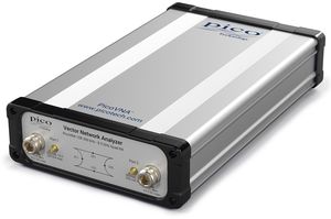


Pico Technology VNA 108
Analyseur de réseau vectoriel 8.5 GHz - USB - dynamique 124dB, bruit 0.005dB RMS max - sauvegarde sur déclenchement, correction VSWR
Analyseur de réseau vectoriel.
Piloté par ordinateur via interface USB 2.0.
Source 300 kHz à 8.5GHz.
Double port.
Bande passante de mesure: sélectionnable de 10Hz à 140kHz.
Résolution: 10Hz.
Dynamique 124dB.
Bruit de 0.0008dB à 0.005 dB max selon la bande passante.
>5000 s-paramètres par seconde.
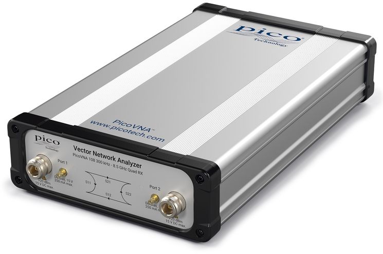
Architecture "Quad RX" (4 récepteurs) pour plus de précision.
Connecteurs en façade: Types N et SMA.
Alimentation par adaptateur secteur.
Requiert un ordinateur sous Windows 7, 8 ou 10 avec 2Go de RAM minimum.
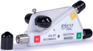
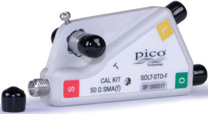
Kits de calibration disponibles en produits associés.
Pour connaître les modèles et quantités ainsi que les cordons et adaptateurs....conseillés/nécessaires selon votre application, voir les pages 4 à 7 de la documentation (datasheet) téléchargeable depuis cette fiche (voir l'onglet "Fichiers à télécharger").
Piloté par ordinateur via interface USB 2.0.
Source 300 kHz à 8.5GHz.
Double port.
Bande passante de mesure: sélectionnable de 10Hz à 140kHz.
Résolution: 10Hz.
Dynamique 124dB.
Bruit de 0.0008dB à 0.005 dB max selon la bande passante.
>5000 s-paramètres par seconde.
Architecture "Quad RX" (4 récepteurs) pour plus de précision.
Connecteurs en façade: Types N et SMA.
Alimentation par adaptateur secteur.
Requiert un ordinateur sous Windows 7, 8 ou 10 avec 2Go de RAM minimum.
Kits de calibration disponibles en produits associés.
Pour connaître les modèles et quantités ainsi que les cordons et adaptateurs....conseillés/nécessaires selon votre application, voir les pages 4 à 7 de la documentation (datasheet) téléchargeable depuis cette fiche (voir l'onglet "Fichiers à télécharger").
VAT incl VAT excl
Quantity
Expédié sous 3 semaines
Quick quote for this product
Quick quote for this product
Details
PicoVNA Series
Vector Network Analyzers
High performance, portability and low cost
- 300 kHz to 6 or 8.5 GHz operation
- High speed of up to 5500 dual-port S-parameters per second
- Over 10000 S11 + S21 per second
- Quad RX four-receiver architecture for optimal accuracy
- Up to 124 dB dynamic range at 10 Hz bandwidth
- 0.005 dB RMS trace noise at maximum bandwidth of 140 kHz
- Half-rack, small-footprint, lightweight package
- PC-controlled over USB from a Microsoft Windows interface
- Reference plane offsetting and de-embedding
- Time-domain and port impedance transformations
- Tabular and graphic print and save formats, including Touchstone
- Save on trigger for high-speed device profiling (PicoVNA 108)
- Dual-frequency mixer measurements with VSWR correction (PicoVNA 108)
- P1dB, AM to PM, and standalone signal generator utilities
- Guided 8- and 12-term and absolute power calibration processes
- 6 calibration modes, including unknown through and connected DUT isolation
- Calibration and check standards with data for confident measurements
Vector network analysis for the many
Once the domain of an elite few, microwave measurement has encroached into the lives of scientists, educators, surveyors, inspectors, engineers and technicians alike. Today’s microwave measurements need to be straightforward, portable, accurate, cost-effective and easy to learn.
PicoVNAs are all-new, UK-designed, professional USB-controlled, laboratory grade vector network instruments of unprecedented performance, portability and value for money. Despite their simple outline, small footprint and low cost, the instruments boast a four-receiver architecture to minimize the uncorrectable errors, delays and unreliability of internal transfer switches.
The PicoVNA 108 delivers an exceptional dynamic range of 124 dB at 10 Hz (118 dB for the PicoVNA 106) and less than 0.006 dB RMS trace noise at its maximum operating bandwidth of 140 kHz. The instruments can also gather all four S-parameters at each frequency point in just 182 μs (PicoVNA 106) or 189 μs (PicoVNA 108) or or S11 + S21 in less than 100 μs. In other words, a 201 point 2-port .s2p Touchstone file in less than 38 ms or up to two .s1p files in less than 20 ms. Their low price makes them cost-effective as deep dynamic range scalar network analyzers or single-port vector reflectometers as well as full-function dual-port, dual-path vector network analyzers. They are affordable in the classroom, in small businesses and even in amateur workshops, yet capable of meeting the needs of all users up to the laboratory or production test technician or the metrology expert.
Vector network analysis everywhere
The PicoVNAs' small size, light weight and low cost suit them to field service, installation test, OEM embedded and classroom applications. With their remote automation capability, they are also attractive in applications such as:
- Test automation, including multiple VNA control and measurement
- Manufacturers needing to integrate a reflectometry or transmission measurement core
- Inspection, test, characterization and calibration in the manufacture, distribution and service center industries:
- Electronics component, assembly and systems, and interface/interconnect ATE (cable, PCB and wireless)
- Material, geological, life-science and food sciences; tissue imaging; penetrating scan and radar
- Broadband cable and harness test and matching at manufacture and installation, and fault-over-life monitoring
- Antenna matching and tuning
Software development kits, including code examples in MATLAB and MATLAB RF toolbox, LabVIEW, C, C# and Python, are all available for download from Pico Technology’s GitHub pages. Examples include multiple instrument addressing and control.
6 GHz Network Metrology Training and Metrology Kits
In the classroom, Pico supports Network Metrology education through a low-cost, potentially one-per-student classroom kit. The Network Metrology Training Kit comprises PCB based passive and active circuit and transmission line examples, calibration standards and test leads, and for Microwave Office users, the project files used in its design. Just add the PicoVNA to start making and learning about network measurements and their critical role within the Design-Simulate-Implement-Measure design cycle.
Specifications
Standard conditions: 10 Hz resolution bandwidth, at 13 dBm (PicoVNA 106) or 0 dBm (PicoVNA 108) test power, at an ambient temperature of between 20°C and 30°C but within 1°C of the calibration temperature and 60 minutes after power-up.
| Receiver characteristics | |||||||||
|---|---|---|---|---|---|---|---|---|---|
| Parameter | Value (PicoVNA 106) | Value (PicoVNA 108) | Conditions | ||||||
| Measurement bandwidth | 140 kHz, 70 kHz, 35 kHz, 15 kHz, 10 kHz, 5 kHz, 1 kHz, 500 Hz, 100 Hz, 50 Hz, 10 Hz | ||||||||
| Average displayed noise floor |
|
|
Relative to the test signal level set to maximum power after an S21 calibration. Ports terminated as during the isolation calibration step. |
||||||
| Dynamic range |
See dynamic range in the product features. Excludes crosstalk. |
10 Hz bandwidth |
|||||||
| Temperature stability, typical | 0.02 dB/ °C for F < 4 GHz 0.04 dB/ °C for F ≥ 4 GHz |
Measured after an S21 calibration | |||||||
| Trace noise, dB RMS |
|
201-point sweep covering 1 MHz to 6 GHz or 8.5 GHz. Test power set to 0 dBm. |
|||||||
| Measurement uncertainty | See table below | Test level of –3 dBm No averaging Bandwidth 10 Hz Ambient temperature equal to the calibration temperature. A 12 error term calibration is assumed carried out with a good quality 3.5 mm calibration kit capable of achieving the performance specified. |
|||||||
| Spurious responses | –76 dBc typical, –70 dBc max. | The main spurious response occurs at close to (2 x RF + 1.3) MHz, where RF is the test frequency in MHz. For example, when testing a bandpass filter with a centre frequency of, say 1900 MHz, an unwanted response will occur around 949.35 MHz. There may also be spurious responses close to (3 x RF + 2.6) MHz. In all known cases the levels will be as stated. | |||||||
| Measurement uncertainty - value | |||||
|---|---|---|---|---|---|
| PC3.5 test port interfaces | |||||
| Reflection measurements | Transmission measurements | ||||
| Freq. range | Magnitude | Phase | Freq. range | Magnitude | Phase |
| –15 dB to 0 dB | 0 dBm to +6 dBm | ||||
| < 2 MHz | 0.7 dB | 8° | < 2 MHz | 0.4 dB | 6° |
| > 2 MHz | 0.5 dB | 4° | > 2 MHz | 0.2 dB | 2° |
| –25 dB to –15 dB | –40 dB to 0 dB | ||||
| < 2 MHz | 0.8 dB | 6° | < 2 MHz | 0.2 dB | 2° |
| > 2 MHz | 1.0 dB | 6° | > 2 MHz | 0.1 dB | 1° |
| –30 dB to –25 dB | –60 dB to –40 dB | ||||
| < 2 MHz | 3.0 dB | 20° | < 2 MHz | 0.5 dB [106] 0.3 dB [108] |
8° |
| > 2 MHz | 2.5 dB [106] 3.0 dB [108] |
15° 20° |
> 2 MHz | 0.3 dB | 4° |
| –80 dB to –60 dB | |||||
| < 2 MHz | 2.0 dB | 15° | |||
| > 2 MHz | 1.5 dB | 12° | |||
| SMA test port interfaces | |||||
| –15 dB to 0 dB | +0 dBm to +6 dBm | ||||
| < 2 MHz | 0.99 dB | 11.3° | < 2 MHz | 0.57 dB | 8.5° |
| > 2 MHz | 0.71 dB | 5.7° | > 2 MHz | 0.28 dB | 2.8° |
| –25 dB to –15 dB | –40 dB to 0 dB | ||||
| < 2 MHz | 1.13 dB | 14.1° | < 2 MHz | 0.42 dB | 2.8° |
| > 2 MHz | 1.41 dB | 8.5° | > 2 MHz | 0.14 dB | 1.4° |
| –30 dB to –25 dB | –60 dB to –40 dB | ||||
| < 2 MHz | 4.24 dB | 28.3° | < 2 MHz | 0.71 dB | 11.3° |
| > 2 MHz | 3.54 dB | 21.2° | > 2 MHz | 0.42 dB | 5.7° |
| –80 dB to –60 dB | |||||
| < 2 MHz | 2.83 dB | 21.2° | |||
| > 2 MHz | 2.12 dB | 17.0° | |||
| Test port characteristics | |||||||||
|---|---|---|---|---|---|---|---|---|---|
| Parameter | PicoVNA 106 | PicoVNA 108 | Conditions | ||||||
| Load match |
|
||||||||
| Source match |
|
||||||||
| Directivity |
|
||||||||
| Crosstalk |
|
|
Corrected. Both calibrated ports terminated in short circuits. After isolation calibration. |
||||||
| Maximum input level | +10 dBm, typ | 0.1 dB compression | |||||||
| Maximum input level | +20 dBm | +23 dBm | No damage | ||||||
| Impedance | 50 Ω | ||||||||
| Connectors | Type N(f) | ||||||||
| Bias-T input characteristics | |||
|---|---|---|---|
| Parameter | PicoVNA 106 | PicoVNA 108 | Conditions |
| Maximum current | 250 mA | ||
| Maximum DC voltage | ±15 V | ||
| Current protection | Built-in resettable fuse | ||
| DC port connectors | SMB(m) | ||
| Sweep I/O characteristics | |||
|---|---|---|---|
| Sweep trigger output voltage | Low: 0 V to 0.8 V High: 2.2 V to 3.6 V |
||
| Sweep trigger input voltage | Low: –0.1 V to 1 V High: 2.0 V to 4 V |
||
| Sweep trigger input voltage | ±6 V | No damage | |
| Sweep trigger in/out connectors | BNC(f) on back panel | ||
| Measuring functions | |||
|---|---|---|---|
| Measuring parameters | S11, S21, S22, S12 P1dB (1 dB gain compression) AM-PM conversion factor (PM due to AM) Mixer conversion loss, return loss, isolation and compression (PicoVNA 108 only) |
||
| Error correction | 12 error term full S-parameter correction (insertable DUT) 12 error term full S-parameter correction (non-insertable DUT) 8 error term full S-parameter unknown thru correction (non-insertable DUT) S11 (1-port correction) De-embed (2 embedding networks may be specified), impedance conversion S21 (normalize, normalize + isolation) S21 (source match correction + normalize + isolation) Averaging, smoothing Hanning and Kaiser–Bessel filtering on time-domain measurements Electrical length compensation (manual) Electrical length compensation (auto) Effective dielectric constant correction |
||
| Display channels | 4 channels | ||
| Traces | 2 traces per display channel | ||
| Display formats | Amplitude (logarithmic and linear) Phase, Group Delay, VSWR, Real, Imaginary, Smith Chart, Polar, Time Domain |
||
| Memory trace | One per display channel | ||
| Limit lines | 6 segments per channel (overlap allowed) | ||
| Markers | 8 markers | ||
| Marker functions | Normal, Δ marker, fixed marker, peak / min. hold, 3 dB and 6 dB bandwidth | ||
| Sweep functions | ||||||||||||||||||||||||
|---|---|---|---|---|---|---|---|---|---|---|---|---|---|---|---|---|---|---|---|---|---|---|---|---|
| Parameter | PicoVNA 106 | PicoVNA 108 | Conditions | |||||||||||||||||||||
| Sweep type | Linear sweep CW sweep (timed sweep) Power sweep (P1dB utility) |
|||||||||||||||||||||||
| Sweep times |
|
10 MHz to 6 GHz or 8.5 GHz, 201-point trace length. For other lengths and bandwidths, sweep time is approximately: |
||||||||||||||||||||||
| Number of sweep points, VNA mode | 51, 101, 201, 401, 801, 1001, 2001, 4001, 5001, 6001, 7001, 8001, 9001,10001 | |||||||||||||||||||||||
| Number of sweep points, TDR mode | 512, 1024, 2048, 4096 | |||||||||||||||||||||||
| Signal source characteristics | |||||||||||||
|---|---|---|---|---|---|---|---|---|---|---|---|---|---|
| Parameter | PicoVNA 106 | PicoVNA 108 | Conditions | ||||||||||
| Frequency range | 300 kHz to 6.0 GHz | 300 kHz to 8.5 GHz | |||||||||||
| Frequency setting resolution | 10 Hz | ||||||||||||
| Frequency accuracy | 10 ppm max | With ambient of 23 ±3 °C | |||||||||||
| Frequency temperature stability | ±0.5 ppm/ºC max | Over the range +15 °C to +35 °C | |||||||||||
| Harmonics | –20 dBc max | With test power set to < –3 dBm | |||||||||||
| Non-harmonic spurious | –40 dBc typical | ||||||||||||
| Phase noise (10 kHz offset) | 0.3 MHz to 1 GHz: –90 dBc/Hz 1 GHz to 4 GHz: –80 dBc/Hz > 4 GHz: –76 dBc/Hz |
||||||||||||
| Test signal power |
|
|
|||||||||||
| Power setting resolution | 0.1 dB | ||||||||||||
| Power setting accuracy | ±1.5 dB | ||||||||||||
| Reference input frequency | 10 MHz ±6 ppm | ||||||||||||
| Reference input level | 0 ±3 dBm | ||||||||||||
| Reference output level | 0 ±3 dBm | ||||||||||||
| Miscellaneous | |
|---|---|
| Controlling PC data interface | USB 2.0 |
| Support for third party test software | Dynamic Link Library (DLL) as part of user interface software |
| External dimensions (mm) | 286 x 174 x 61 (L x W x H) Excluding connectors |
| Weight | 1.9 kg |
| Temperature range (operating) | +5 °C to +40 °C |
| Temperature range (storage) | –20 °C to +50 °C |
| Humidity | 80% max, non-condensing |
| Vibration (storage) | 0.5 g, 5 Hz to 300 Hz |
| Power source and current | +12 to +15 V DC, 22 W (PicoVNA 106) / 25 W (PicoVNA 108) |
| Power source connector | 5.5 mm diameter hole, 2.1 mm diameter centre contact pin. Centre pin is positive. |
| Host PC requirements | Microsoft Windows 7, 8 or 10 2 GB RAM or more |
| Safety | Conforms to EN61010-1:2010 and EN61010-2-030:2010 |
| Warranty | 3 years |
Product Details
| 41-Standard Manufacturer Warranty | 3 YEARS |
| 235-Frequency (max) | 8.5 GHz |
| 613-RF Connector | N |
| 35-Dimension (HxWxD) (mm) | 61x174x286 mm |
| 13-Net Weight | 1.9 kg |
| En Stock | No |
Download Files
Associated Products

Related Products
Items already seen